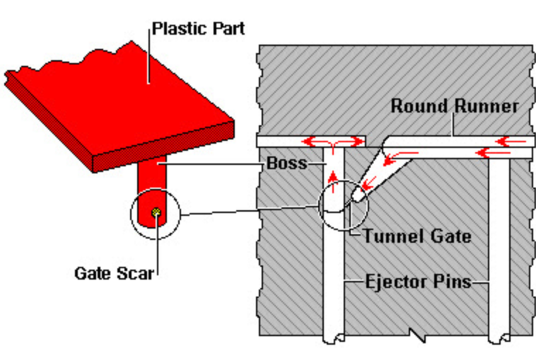
In plastic injection molding, the “gate” is the opening in a mold through which the molten plastic is forced into the cavity, the tooling representation of your part. The type of gate and its location are critical, they can make or break a part. The placement of the gate can also affect many aspects of a project. So how can we choose the right gate location for mold? Check out this article and get to know the gate on injection mold and gate location selecting skills & tips.

Requirements For Gate Location Injection Molding
Gate design is related to the size, shape, mold structure, injection process conditions and performance of plastic parts. But in terms of the basic function, the gate section should be small and the length should be short, because only in this way can the requirements of increasing the material flow speed, rapid cooling and sealing, facilitating the separation of plastic parts and minimizing the residual mark of the gate. There are five requirements for gate placement in mold:
1. Appearance requirements (gate trace and welding line);
2. Product function requirements;
3. Mold processing requirements;
4. Warpage of products;
5. The gate capacity is not easy to remove.
Impact On Production And Function
1. Low length
The flow length determines the injection pressure, the mold locking force, and the full filling of the product. The short flow length can reduce the injection pressure and the mode locking force.
2. Gate location
The gate location will affect the pressure maintaining pressure, the pressure maintaining pressure and the balance of the pressure retaining pressure. Keep the gate away from the stress position of the product to avoid residual stress, vent must be considered in the gate location to avoid cavitation. Do not place the gate at the weak or embedded part of the product to avoid deviation.
Skills & Tips For Choosing Gate Location For Mold
1. Gate
Gate is a small cross-sectional area of the short slot, used to connect the runner and mold cavity. Therefore, the cross-sectional area should be small in order to achieve the following effects:
● After injection molding, the gate will be cold bonded.
● The water outlet is simple.
● Only a few traces are left after the water outlet is finished.
● The packing of multiple cavities is easy to control.
● Reduce the phenomenon of excessive packing.
2. Gate location and size
● Place the gate at the thickest part of the product. Pouring from the thickest part can provide better filling and pressure retaining effect. If the pressure is not enough, the thinner area will solidify more quickly than the thicker area, so as to avoid placing the gate at the sudden change of thickness, so as to avoid the occurrence of hysteresis or short shot.
● If possible, pour from the center of the product. Placing the gate in the center of the mold product can provide equal length of flow, which will affect the required injection pressure. The central pouring makes the pressure of each direction uniform, which can avoid the uneven volume shrinkage.
● When the plastic flows into the runner, the plastic cools and solidifies first near the mold surface. When the plastic flows forward, only the layer of plastic that solidifies here flows through. Because the plastic is a low heat transfer material, the solid plastic forms an insulation layer, and the melt in the middle can still flow.
Therefore, in an ideal situation, the gate should be set in the cross runner layer to produce the best plastic flow effect.
The following principles should be followed when determining the gate location:
– The amount of compound injected into each part of the cavity should be as uniform as possible.
– The flow front should be uniform and stable in all stages of the injection process.
– The possible weld lines, bubbles, pits, virtual positions, insufficient glue injection and glue spraying should be considered.
– The location of the gate should be compatible with all aspects.
3. Injection moulding gate size
The injection molding gate size can be determined by the cross-sectional area and gate length, and the optimal gate size can be determined by the following factors:
● The thickness of the mold product.
● The amount of rubber injected into the cavity.
● Melting temperature.
● Mold temperature.
Gate Balance
If you can’t obtain balanced runner system, the following gate balancing method can be used to achieve the goal of balanced injection mold. This method is suitable for the mould with a large number of cavities.
There are two methods of gate balancing: changing the length of gate channel and changing the cross-sectional area of gate. In another case, the gate needs to be balanced when the cavity has different projected areas. At this time, in order to determine the size of the gate, it is necessary to determine the size of one of the gates and find out the ratio of its corresponding cavity volume, and apply this ratio to the comparison between the gate and each corresponding cavity, and then the size of each gate can be calculated successively. After the actual trial injection, the gate balancing operation can be completed.
Direct Gate & Sprue Gate
The sprue supplies plastic directly to the finished injection molded product, and the runner adheres to the finished product. In a two plate mold, the sprue gate is usually one out of one. The sprue gate is rarely used in the design of three plate mold or hot runner mold.
Gate Selection
The gate is the connecting part between the runner and the cavity, and also the last part of the injection mold feeding system, the basic functions are as follows:
1. Make the molten plastic from the runner enter the filling cavity at the fastest speed.
2. After the cavity is full, the gate can be quickly cooled and closed to prevent the return of the uncooled plastics in the cavity.
